The High Temperature Test Facility [HTTF]
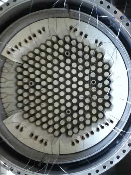
The Oregon State University HTTF is a highly instrumented, reduced-scale, thermal hydraulics testing facility used to collect validation data for a range of transient flow scenarios for the high temperature gas reactor [HTGR] class of commercial nuclear power plants. The facility's scaling is based on the bulk flow parameters and thermal hydraulic characteristics of the Modular High Temperature Gas Reactor [MHTGR]. The facility was constructed over a three year period, from 2013 to 2016, and is currently executing a testing program and collecting data for a prismatic-block core configuration.
My involvement with the HTTF began in 2012 and continued until 2018. I've worked on every system which comprises the facility and managed development tasks covering a wide variety of engineering disciplines to support the ongoing function of the facility and future hardware adjustments which have become necessary. Through my involvement, I've become experienced with many facets of developing and executing an experimental testing program. This includes soft skills such as quality assurance, personnel training and management, and budget and expense forecasting; as well as technical proficiency related to the experimental instrumentation systems and analysis. Instrumentation tasks were related to system development, installation, termination and testing of multiple classes of sensors for a variety of measurement applications. The primary result of my time with the HTTF is a thorough and robust understanding of experimental thermal hydraulic methods, as well a an expertise in large scale experimental instrumentation systems.




FAcility Vessel installation
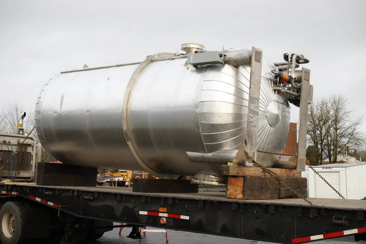
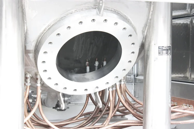
The vessels and piping which constitute the HTTF were fabricated by Harris Thermal Transfer Products and were shipped from their facility and installed at the testing location in 2013 and 2014. The two primary tanks are the reactor cavity simulation tank (RCST) and the primary pressure vessel (PPV).
After delivery, all heavy lifting and installation tasks were managed by our team. These tasks required knowledge of rigging and load maneuvering, as well as compliance with all safety regulations defined by Oregon State University.
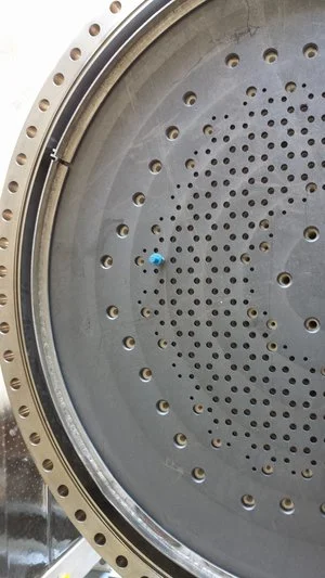
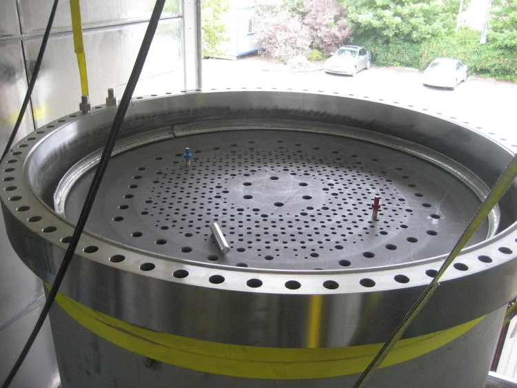
The PPV contains the facility core, which is heated by graphite resistance heaters. The vessel barrel and upper-head are two separate components and are sealed with two large body flanges that are approximately 65 inches in diameter. All vessels are comprised of 304 stainless steel and are certified for high temperature operation.









Facility Core Installation
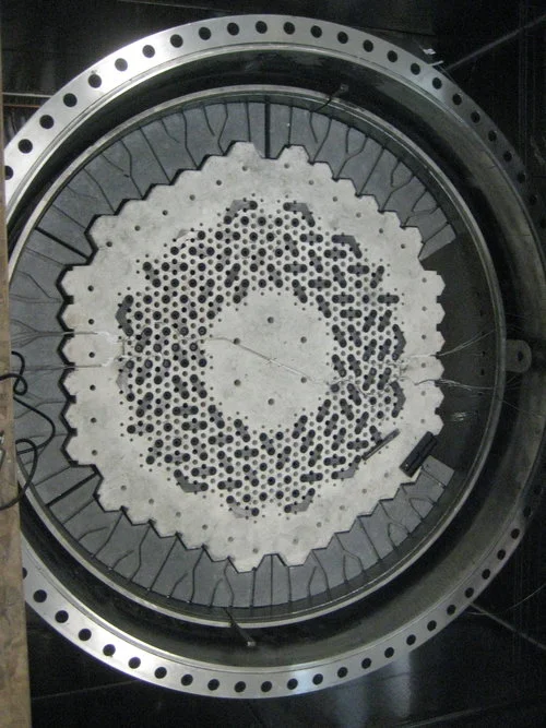
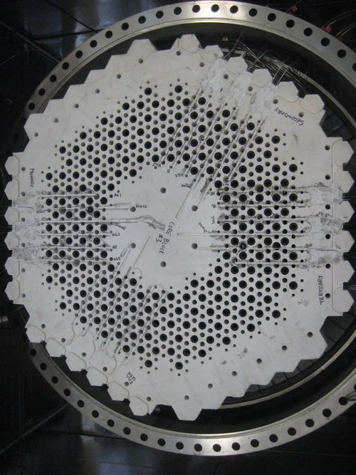
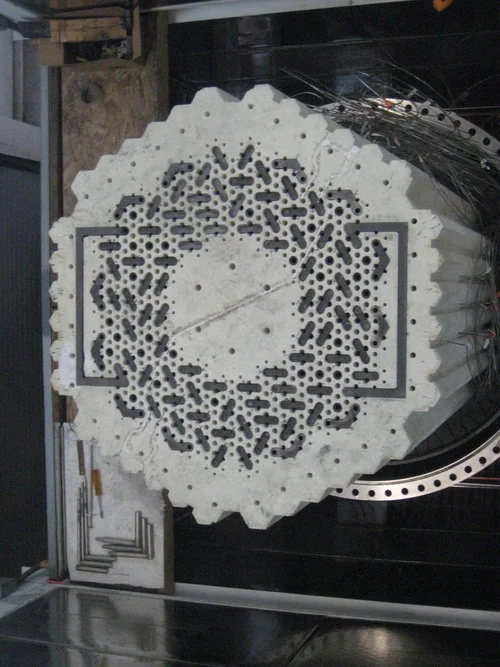
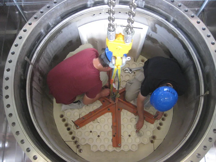
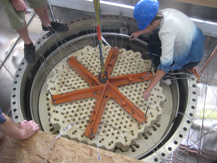
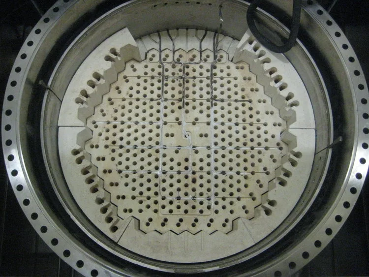
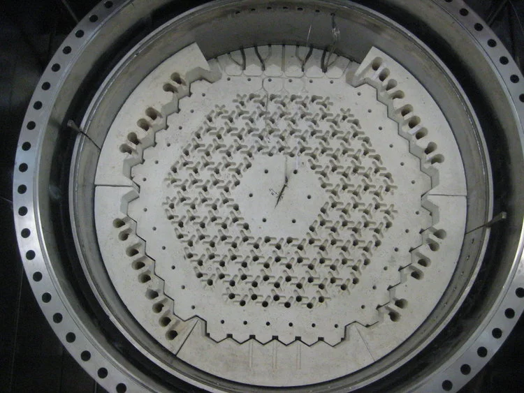
The facility core is comprised of a number of alumina and silicon carbide-based ceramic blocks, which stack together to form a geometry similar to the prismatic block geometry found inside HTGR cores. The ceramic was specifically developed to match thermal transfer parameters determined by the scaling analysis for the the facility.
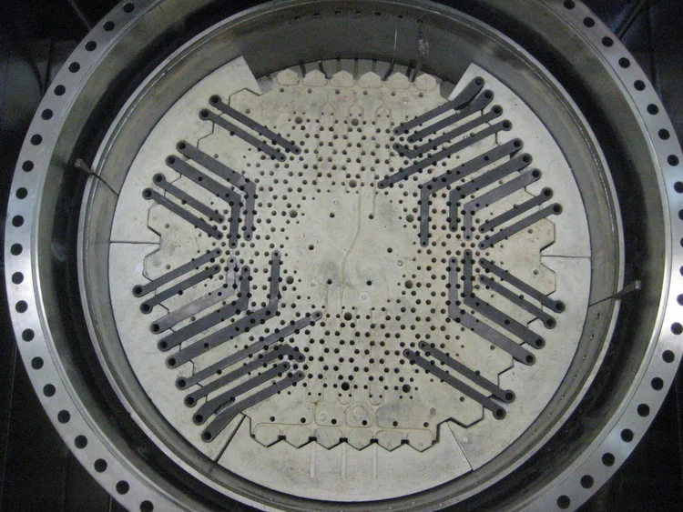
The core is comprised of two primary sections. The lower plenum was assembled first, with a number of posts creating a void which allows gas to flow from the coolant channels into the integrated duct at the bottom of the vessel. The central core region is assembled from stacked core blocks and contains the graphite resistance heating circuit.
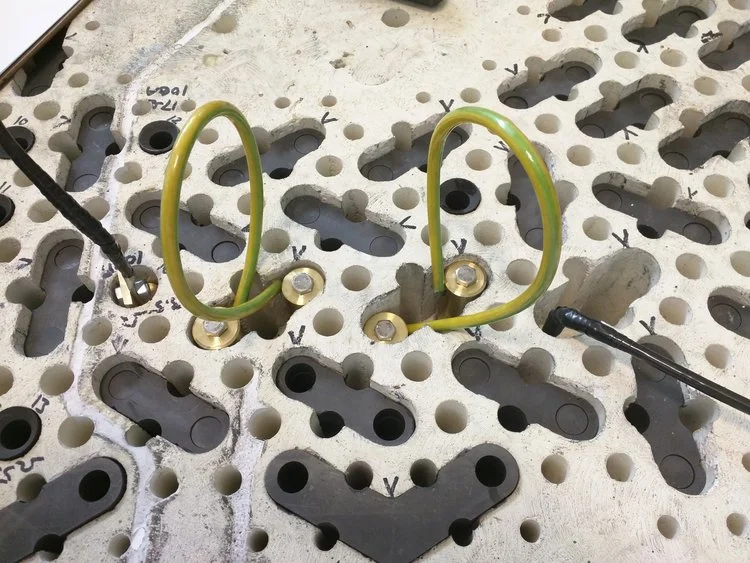
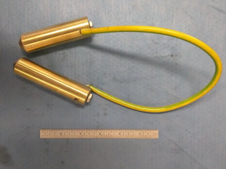
The core contains a high density of instruments which characterize the thermal transfer properties of the core ceramic during simulated flow transients. The instrumentation system includes a large number of K-type and C-type thermocouples, pressure taps, voltage taps, and specially designed gas concentration sensors.




![Convex+graphite+sample+[ridges]_003.png](https://images.squarespace-cdn.com/content/v1/5878603c20099e6cabedd4d4/1519136690419-6V5UTS7XY5OFQSR15FRL/Convex%2Bgraphite%2Bsample%2B%5Bridges%5D_003.png)
HEATER CHARACTERIZATION TESTING
After the resistance heating system for the HTTF was initially installed, performance testing indicated that the design of the upper heater connections was leading to inconsistent contact between the graphite components. To identify the root cause of the problem, a testing program was carried out which isolated the electrical fault that was observed and explored potential design adjustments which would remedy the issue.
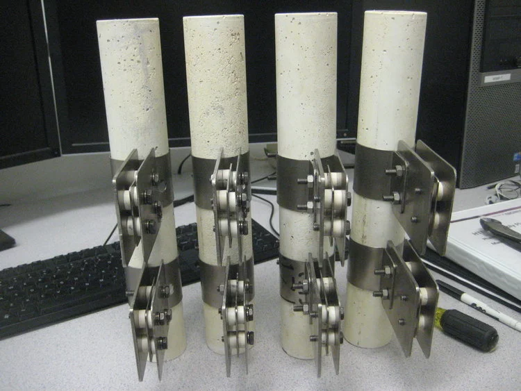
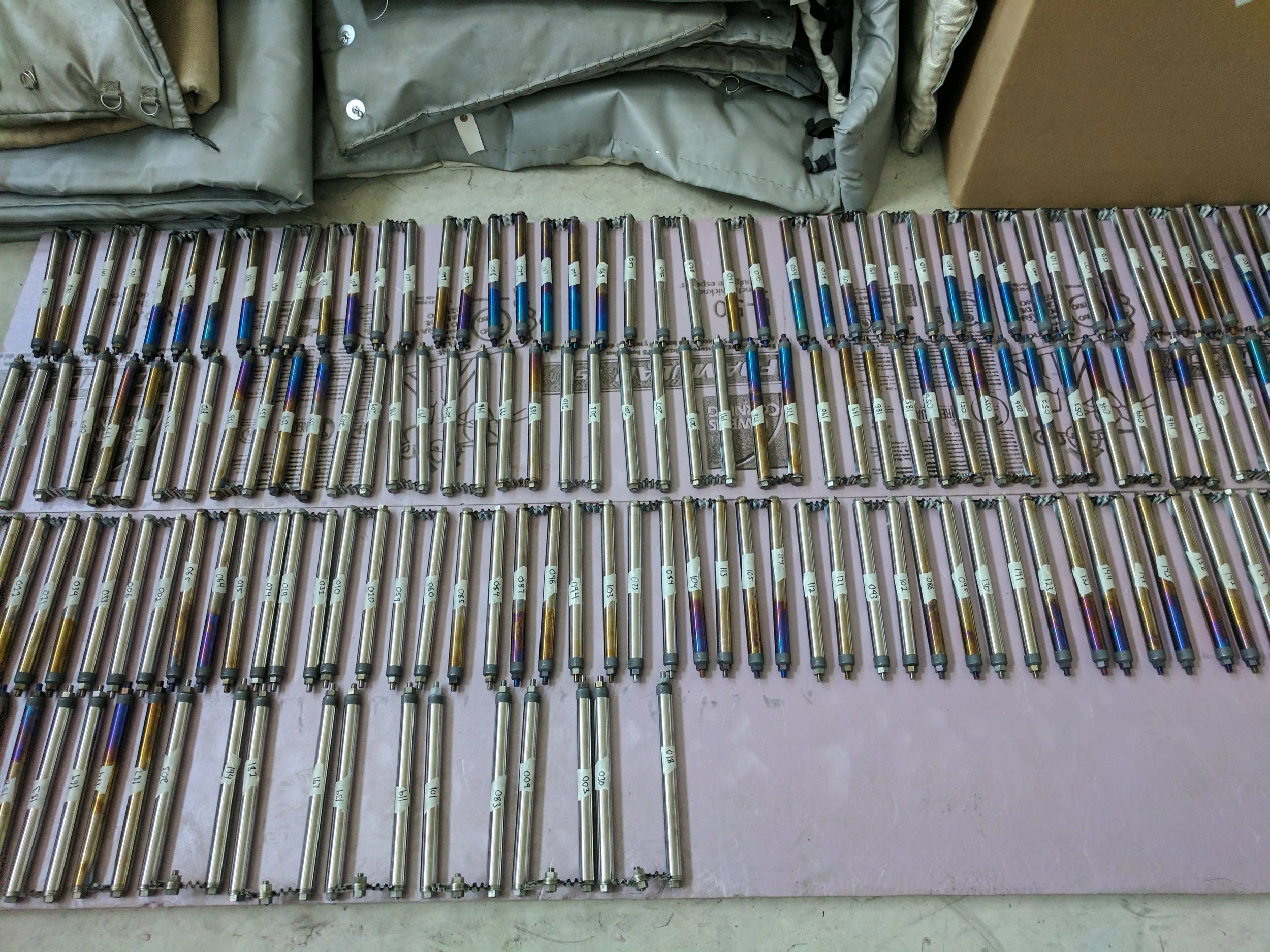
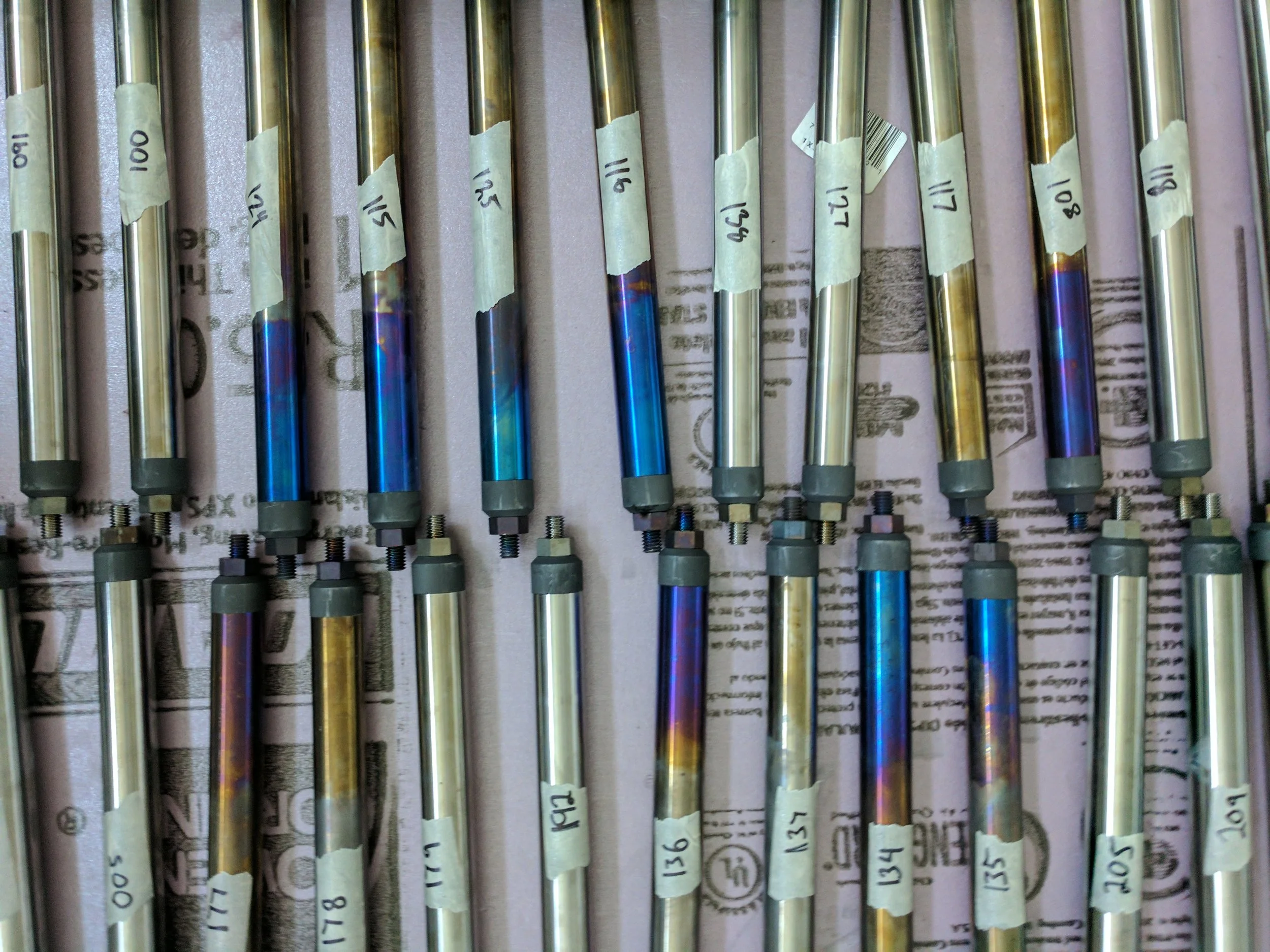
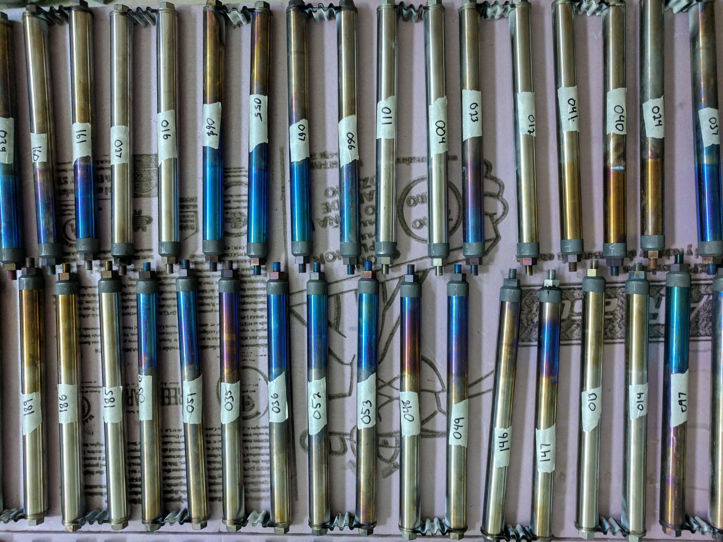
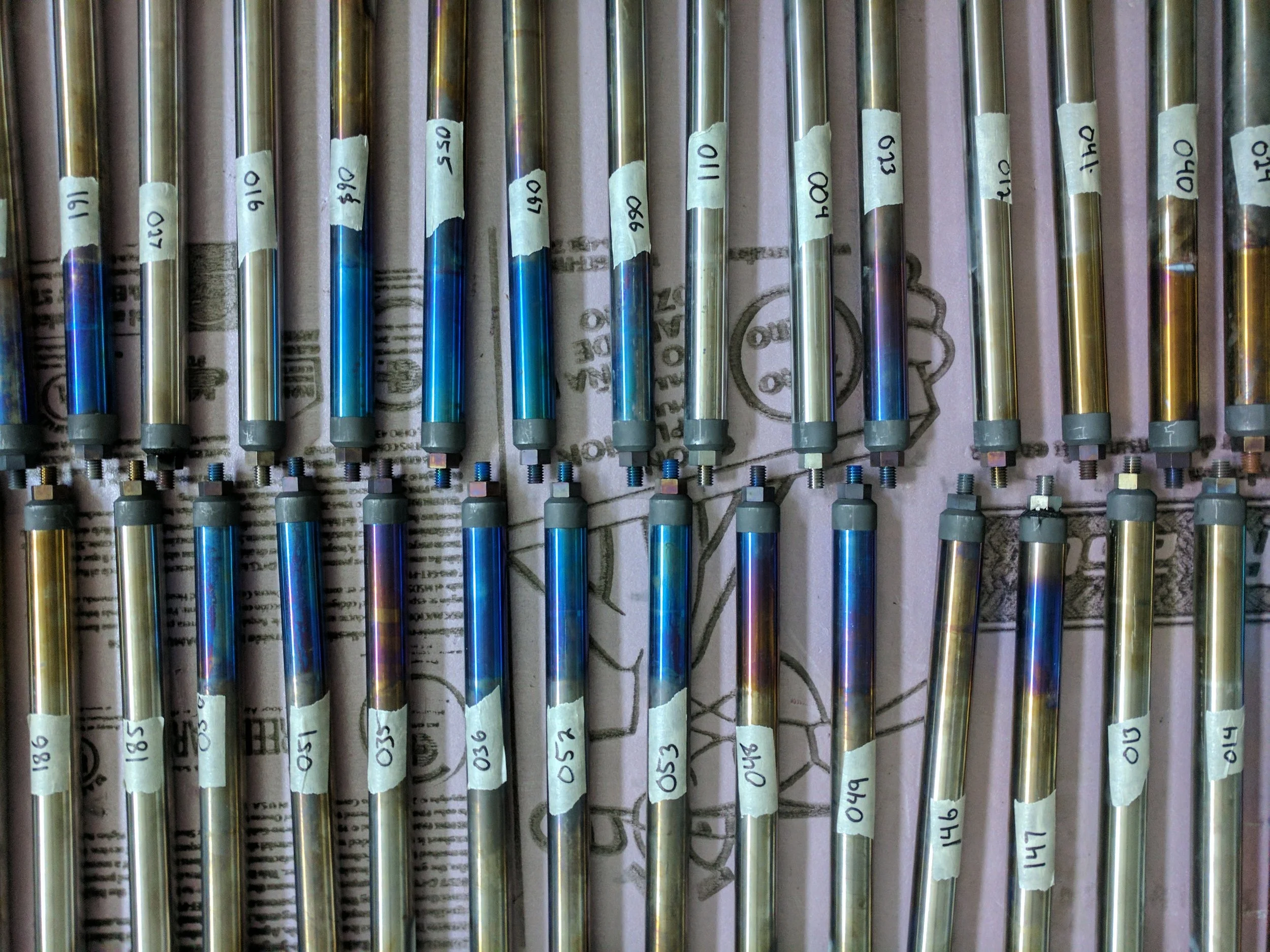
Stainless steel prototype components were fabricated in-house, allowing for rapid testing of potential geometry changes and selection of an alternative heater assembly that would ensure good contact between all electrical interfaces and allow for consistent performance of the heaters. Final fabrication of the components was performed by a specialized manufacturer due to the difficulty in machining the tungsten alloy that was selected as the ideal material for the new components.
This testing program also resulted in a characterization for the wear-in of the graphite components used. A scanning electron microscope was used to take images of the graphite interfaces before and after axial loading, and an adjustable loading apparatus was designed to simulate increasing loads while the circuit is being powered. The results of this testing were summarized in a journal article presented at the 2015 Annual Meeting of the American Nuclear Society.


Heater Circuit Hardware Upgrade
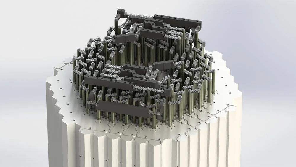
Once potential sources of failure were identified and characterized by the targeted testing program, development of a potential hardware modification to address the problem began. This included the testing of multiple interface designs and a number of unique approaches for the application of a compression force on the graphite interfaces of the heater rodlet stack.
The final upper junction assemblies utilized a heavy tungsten rodlet placed at the top of the graphite rodlet stack, which provided a constant compression force for the graphite interfaces. These tungsten rodlets were designed to move, both axially and radially, as the heater circuit heats and cools. This adaptability is enabled by the use of stacked sets of thin bands of flexible molybdenum which connect each part of the assembly. This approach provides a novel solution to the described problem and has resulted in consistent heater performance since the modification was made in 2015 and 2016.
Files
A presentation that provides a good overview of the electrically heated core: Core Geometry Overview
A presentation which describes some of the development work for the heater circuit upgrade: Heater Circuit Upgrade Report
A presentation, authored by the principle investigator of the project, that describes the general details of the facility: HTTF Overview
An example of a presentation given as an experimental update, also authored by the principle investigator of the project: HTTF Experimental Update


